- 您现在的位置:买卖IC网 > Sheet目录2004 > LTC1545CG (Linear Technology)IC TXRX SOFTWARE SELECTBL 36SSOP
11
LTC1545
APPLICATIONS INFORMATION
WU
U
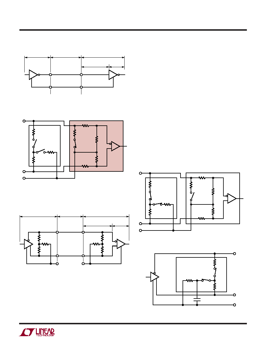
Figure 16. Typical V.28 Interface
AA
'
CC
'
GENERATOR
BALANCED
INTERCONNECTING
CABLE
LOAD
CABLE
TERMINATION
RECEIVER
1545 F16
V.35 interface requires a T or delta network termination at
the receiver end and the generator end. The receiver
differential impedance measured at the connector must be
100
±10, and the impedance between shorted termi-
nals (A
' and B') and ground C' must be 150
±15.
In V.35 mode, both switches S1 and S2 inside the LTC1344A
are on, connecting the T network impedance as shown in
Figure 19. Both switches in the LTC1543 are off. The 30k
input impedance of the receiver is placed in parallel with
the T network termination, but does not affect the overall
input impedance significantly.
The generator differential impedance must be 50
to
150
and the impedance between shorted terminals (A
and B) and ground C must be 150
±15. For the
generator termination, switches S1 and S2 are both on and
the top side of the center resistor is brought out to a pin so
it can be bypassed with an external capacitor to reduce
common mode noise as shown in Figure 20.
Figure 20. V.35 Driver Using the LTC1344A
V.35 DRIVER
A
B
C
51.5
S2
ON
S1
ON
1545 F20
51.5
LTC1344A
124
C1
100pF
R3
124
R5
20k
LTC1344A
LTC1543
RECEIVER
1545 F19
A
B
A
'
B
'
C
'
R1
51.5
R8
6k
S2
S3
R2
51.5
R6
10k
R7
10k
GND
R4
20k
S1
Figure 19. V.35 Receiver Configuration
V.35 Interface
A typical V.35 balanced interface is shown in Figure 18. A
V.35 differential generator with outputs A and B with
ground C is connected to a differential receiver with
ground C
', inputs A' connected to A, B' connected to B. The
Figure 18. Typical V.35 Interface
A
'
B
C
B
'
C
'
GENERATOR
BALANCED
INTERCONNECTING
CABLE
LOAD
CABLE
TERMINATION
RECEIVER
1545 F18
50
125
50
50
125
50
Figure 17. V.28 Receiver Configuration
R3
124
R5
20k
LTC1344A
LTC1543
LTC1545
RECEIVER
1545 F17
A
B
A
'
B
'
C
'
R1
51.5
R8
6k
S2
S3
R2
51.5
R6
10k
R7
10k
GND
R4
20k
S1
发布紧急采购,3分钟左右您将得到回复。
相关PDF资料
LTC1590IS#TRPBF
IC D/A CONV 12BIT DUAL 16-SOIC
LTC1592AIG#TRPBF
IC D/A CONV 16BIT SOFTSPAN16SSOP
LTC1595AIN8
IC D/A CONV 16BIT MULTPLYNG 8DIP
LTC1597AIN#PBF
IC CONV D/A 16BIT PAR 28-DIP
LTC1598CG
IC A/D CONV 12BIT SRL 8CH 24SSOP
LTC1598LCG
IC A/D CONV 12BIT SRL 8CH 24SSOP
LTC1599AIG#TRPBF
IC D/A CONV 16BIT MLTPLYNG24SSOP
LTC1603IG#TRPBF
IC ADC W/SHUTDOWN 16BIT 36-SSOP
相关代理商/技术参数
LTC1545CG#PBF
功能描述:IC TXRX SOFTWARE SELECT 36-SSOP RoHS:是 类别:集成电路 (IC) >> 接口 - 驱动器,接收器,收发器 系列:- 标准包装:250 系列:- 类型:收发器 驱动器/接收器数:2/2 规程:RS232 电源电压:3 V ~ 5.5 V 安装类型:表面贴装 封装/外壳:16-TSSOP(0.173",4.40mm 宽) 供应商设备封装:16-TSSOP 包装:带卷 (TR)
LTC1545CG#TR
功能描述:IC TXRX SOFTWARE SELECTBL 36SSOP RoHS:否 类别:集成电路 (IC) >> 接口 - 驱动器,接收器,收发器 系列:- 标准包装:250 系列:- 类型:收发器 驱动器/接收器数:2/2 规程:RS232 电源电压:3 V ~ 5.5 V 安装类型:表面贴装 封装/外壳:16-TSSOP(0.173",4.40mm 宽) 供应商设备封装:16-TSSOP 包装:带卷 (TR)
LTC1545CG#TRPBF
功能描述:IC TXRX SOFTWARE SELECTBL 36SSOP RoHS:是 类别:集成电路 (IC) >> 接口 - 驱动器,接收器,收发器 系列:- 标准包装:250 系列:- 类型:收发器 驱动器/接收器数:2/2 规程:RS232 电源电压:3 V ~ 5.5 V 安装类型:表面贴装 封装/外壳:16-TSSOP(0.173",4.40mm 宽) 供应商设备封装:16-TSSOP 包装:带卷 (TR)
LTC1545IG
功能描述:IC TXRX SOFTWARE SELECTBL 36SSOP RoHS:否 类别:集成电路 (IC) >> 接口 - 驱动器,接收器,收发器 系列:- 标准包装:250 系列:- 类型:收发器 驱动器/接收器数:2/2 规程:RS232 电源电压:3 V ~ 5.5 V 安装类型:表面贴装 封装/外壳:16-TSSOP(0.173",4.40mm 宽) 供应商设备封装:16-TSSOP 包装:带卷 (TR)
LTC1545IG#PBF
功能描述:IC TXRX SOFTWARE SELECTBL 36SSOP RoHS:是 类别:集成电路 (IC) >> 接口 - 驱动器,接收器,收发器 系列:- 标准包装:250 系列:- 类型:收发器 驱动器/接收器数:2/2 规程:RS232 电源电压:3 V ~ 5.5 V 安装类型:表面贴装 封装/外壳:16-TSSOP(0.173",4.40mm 宽) 供应商设备封装:16-TSSOP 包装:带卷 (TR)
LTC1545IG#TR
功能描述:IC TXRX SOFTWARE SELECTBL 36SSOP RoHS:否 类别:集成电路 (IC) >> 接口 - 驱动器,接收器,收发器 系列:- 标准包装:250 系列:- 类型:收发器 驱动器/接收器数:2/2 规程:RS232 电源电压:3 V ~ 5.5 V 安装类型:表面贴装 封装/外壳:16-TSSOP(0.173",4.40mm 宽) 供应商设备封装:16-TSSOP 包装:带卷 (TR)
LTC1545IG#TRPBF
功能描述:IC TXRX SOFTWARE SELECTBL 36SSOP RoHS:是 类别:集成电路 (IC) >> 接口 - 驱动器,接收器,收发器 系列:- 标准包装:250 系列:- 类型:收发器 驱动器/接收器数:2/2 规程:RS232 电源电压:3 V ~ 5.5 V 安装类型:表面贴装 封装/外壳:16-TSSOP(0.173",4.40mm 宽) 供应商设备封装:16-TSSOP 包装:带卷 (TR)
LTC1546CG
功能描述:IC SW TRANSCEIVER W/TERM 28-SSOP RoHS:否 类别:集成电路 (IC) >> 接口 - 驱动器,接收器,收发器 系列:- 标准包装:250 系列:- 类型:收发器 驱动器/接收器数:2/2 规程:RS232 电源电压:3 V ~ 5.5 V 安装类型:表面贴装 封装/外壳:16-TSSOP(0.173",4.40mm 宽) 供应商设备封装:16-TSSOP 包装:带卷 (TR)